How to cut advanced 3D parts with a sheet metal waterjet machine
Beveljet 60 is a 5-axis cutting head made by Water Jet Sweden primarily designed for sheet material cutting, shaping parts with a 0-60 degree cutting angle. But with the programmable z-axis the cutting head can be used for much more advanced cutting jobs. Together with IGEMS new powerful CAD/CAM software for 3D cutting, IGEMS 3D5X, it turns quickly into a smooth free form cutting tool, with the ability to cut materials in different work planes.
Advanced 3D cutting of sheet materials.
The traditional use case for the Beveljet 60 cutting tool is taper angle control, bevel cutting and advanced shaping of sheet materials.
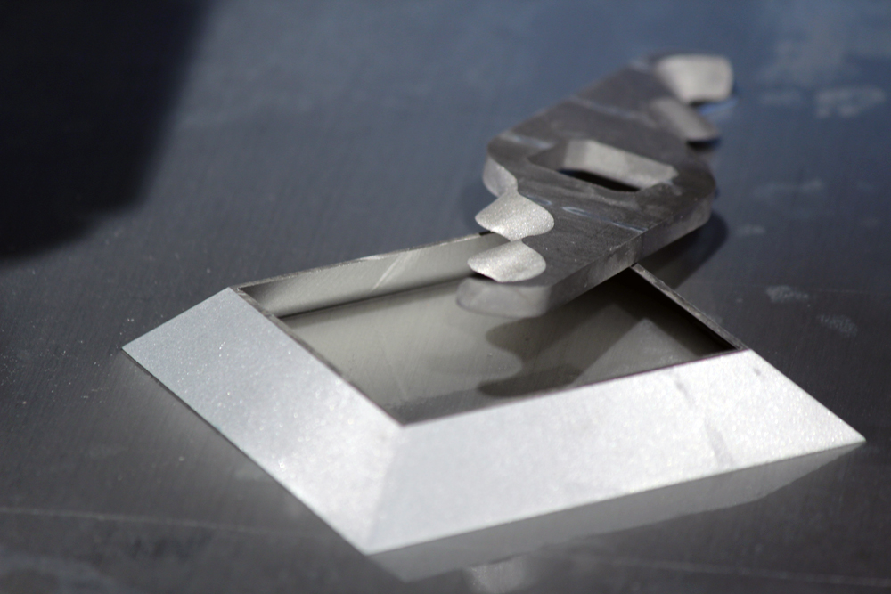
Picture: Advanced parts out of sheet material cut with Beveljet 60.
Since Beveljet 60 has a full 5-axis capability the third-dimension, height, can also be included when there is a need for full 3D cutting jobs, using a 3D CAD/CAM software suitable for the task, such as the new IGEMS 3D5X.
Five steps to full 5-axis shaping of 3D parts
Preparing a free form 3D cutting job for the Beveljet 60 cutting tool is made with a couple of simple steps thanks to the new IGEMS 3D5X software.
Step 1 – Align the part
First of all, the part has to be aligned to suit the machine’s work movement. The Beveljet 60 cutting tool has a 250-mm maximum Z-movement and a 0-60° cutting angle, which make it possible to cut a wide range of 3D parts.
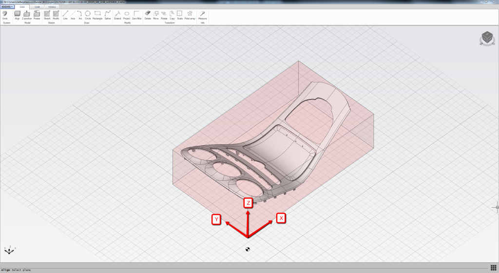
Picture: Part is aligned in IGEMS 3D5X in order to fit the movement of the machine.
Step 2 – Create a fixture
One of the challenges for free form cutting is how to securely fix the workpiece. The “Fixture” function embedded in IGEMS 3D5X makes it easy to generate sheet-based parts to build a complete fixture adapted to the unique part to be processed.
All the parts required for the complete fixture are automatically placed and can be cut as a regular part in suitable sheet material.
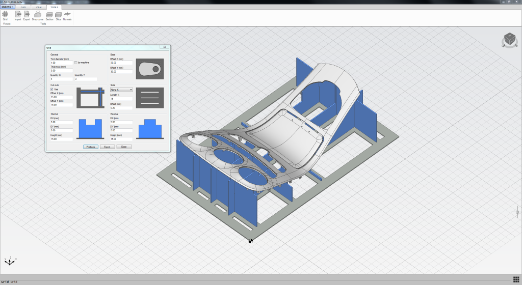
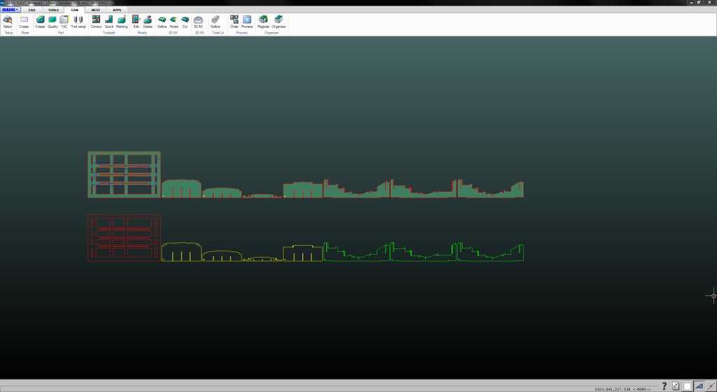
Pictures: The fixture is created in the IGEMS 3D5X software and fixture parts are automatically prepared for cutting.
Step 3 – Prepare the toolpath and movements
A toolpath is added to get the correct cutting angle of geometries to be cut. Several options are available regarding how to align the jet. In this case the “Variable” cut type was selected. In order to save cycle time, the rapid movements between each contour can be adjusted manually.
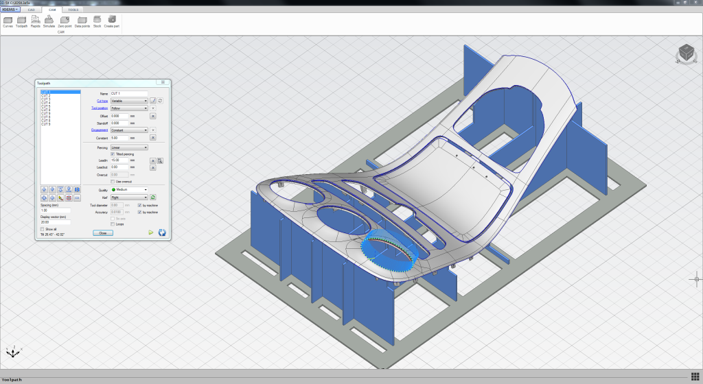
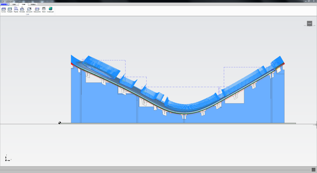
Pictures: Toolpath is added and rapid movement between contours are optimized.
Step 4 – Collision detection test
Beveljet 60 has a 0-60° cutting performance, with a A-axis movement of ± 90° and C-axis movement of ± 400°. The final step is to simulate the cutting job in IGEMS and make a collision detection test, avoiding the cutting head movements interfere with the part.

Picture – simulation with collision detection test in progress
Step 5 – Cut and assemble the fixture
When CAD/CAM programming and test runs are finished the last step before cutting is to build the fixture. Since IGEMS 3D5X automatically prepare the fixture parts it is a normal 2D cutting job in suitable sheet material.
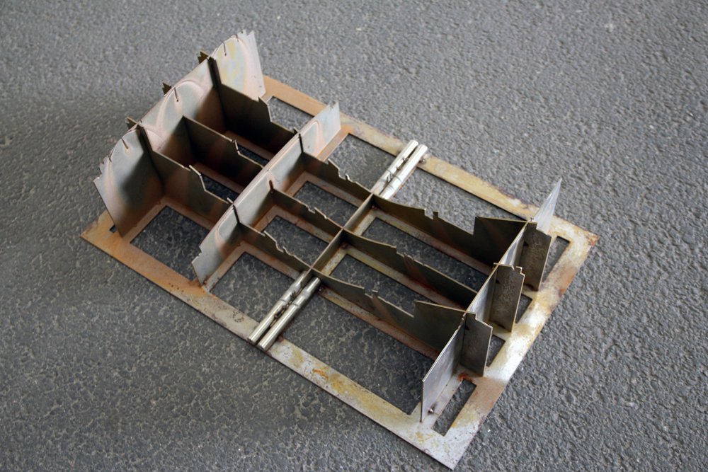
Picture: Fixture made of 2 mm steel, automatically calculated and placed by IGEMS 3D5X.
Cutting parts in different work planes
With IGEMS 3D5X most of Waterjet Sweden ‘s sheet metal cutting machines can be programmed to follow parts with different height automatically during the cutting job. This is also valid for the 2D cutting heads on any machine model.
The example in this article is while cutting a laminated composite material. To avoid delamination the lead ins were pre-drilled, done quickly with a drilling fixture. The advanced 3D shape and cutting requirements was met by using the Belvejet 60 on a NCP Premium machine instead of the full 5-axis head on a NC5 FiveX machine model. Beveljet 60 is available on both Waterjet Jet Sweden Premium and Grand machine models.
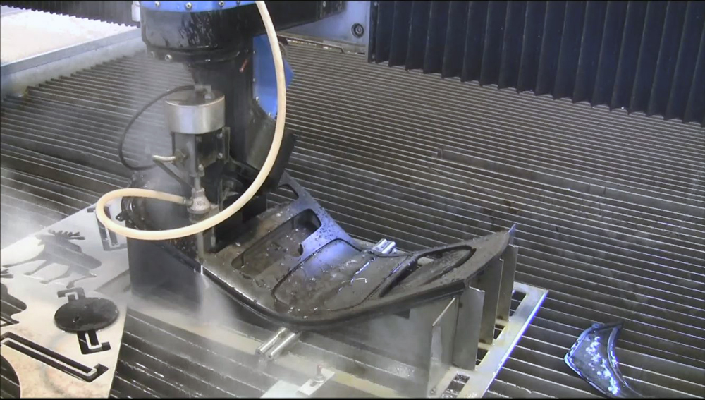
Picture: Finishing off the edges, finalizing the 3D composite part


